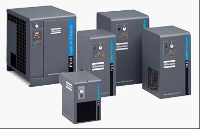
FX 1-16 Refrigerant air dryers
FX refrigerant dryers - the smart choice

The benefits add up :
Solid performance
Steady pressure dew point
No freezing of condensed moisture
No chance of moisture entering the compressed air system.
Simple reliability
Quality components, generously sized
Simple and proven design
Effective control system (hot gas bypass).
Easy Installation
Plug and play concept
Single electrical connection
All units pre-commissioned
Self regulating.
Minimal maintenance
Long service intervals
Few component replacements
Ergonomic design for fast access to key components.
Significant cost savings
Increased reliability and lifetime of tools and equipment
Reduced pipe work leaks, meaning reduced energy bill
Fewer repairs to tools, machines and pipe work
Less inconvenient breakdowns and stoppages
Minimal chance of product spoilage through moisture carryover.
Air purification
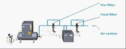
No installation is complete without filtration


Technical data
Technical specification : 50 Hz version
|
Model
|
Outlet pressure dew point
|
Maximum working pressure
|
Electrical supply
|
Compressed air connections
|
|
|
+ 5 °C / 41 °F
|
+ 3 °C / 37 °F
|
|
-
|
|
|
|
Inlet capacity
|
Pressure drop
|
Inlet capacity
|
Pressure drop
|
|
-
|
|
|
|
m³/min
|
bar
|
m³/min
|
bar
|
-
|
|
|
FX 1
|
0.42
|
0.20
|
0.36
|
0.15
|
16
|
230/1/50 Hz
|
3/4" M
|
|
FX 2
|
0.72
|
0.33
|
0.60
|
0.25
|
16
|
230/1/50 Hz
|
3/4" M
|
|
FX 3
|
0.96
|
0.33
|
0.84
|
0.25
|
16
|
230/1/50 Hz
|
3/4" M
|
|
FX 4
|
1.38
|
0.33
|
1.20
|
0.25
|
16
|
230/1/50 Hz
|
3/4" M
|
|
FX 5
|
2.10
|
0.40
|
1.80
|
0.30
|
16
|
230/1/50 Hz
|
3/4" M
|
|
FX 6
|
2.70
|
0.42
|
2.34
|
0.32
|
13
|
230/1/50 Hz
|
1" F
|
|
FX 7
|
3.48
|
0.50
|
3.0
|
0.38
|
13
|
230/1/50 Hz
|
1" F
|
|
FX 8
|
4.15
|
0.24
|
3.60
|
0.18
|
13
|
230/1/50 Hz
|
1 1/2" F
|
|
FX 9
|
4.75
|
0.33
|
4.09
|
0.25
|
13
|
230/1/50 Hz
|
1 1/2" F
|
|
FX 10
|
6.01
|
0.24
|
5.23
|
0.18
|
13
|
230/1/50 Hz
|
1 1/2" F
|
|
FX 11
|
7.51
|
0.26
|
6.49
|
0.20
|
13
|
230/1/50 Hz
|
1 1/2" F
|
|
FX 12
|
8.89
|
0.36
|
7.69
|
0.27
|
13
|
230/1/50 Hz
|
1 1/2" F
|
|
FX 13
|
11.53
|
0.33
|
10.03
|
0.25
|
13
|
400/3/50 Hz
|
2" F
|
|
FX 14
|
13.82
|
0.40
|
12.02
|
0.30
|
13
|
400/3/50 Hz
|
2" F
|
|
FX 15
|
17.30
|
0.40
|
15.02
|
0.30
|
13
|
400/3/50 Hz
|
2" F
|
|
FX 16
|
20.73
|
0.40
|
18.02
|
0.30
|
13
|
400/3/50 Hz
|
2" F
|
Reference conditions
• Ambient temperature : 25 °C • Inlet temperature : 35 °C • Working pressure : 7 bar(g)
Notes :
Refrigerant types: • R134a for FX 1-5 • R404a for FX 6-16
Limitations :
• Max. ambient temp.: 43 °C • Min. ambient temp.: 5 °C • Max. inlet temp.: 55 °C
Filter selection
|
Model
|
Outlet pressure dew point
|
|
|
+ 5 °C / 41 °F
|
+ 3 °C / 37 °F
|
|
|
Inlet capacity
|
Pre filter
|
After filter
|
Inlet capacity
|
Pre filter
|
After filter
|
|
|
l/s
|
-
|
l/s
|
-
|
|
FX 1
|
7
|
DD9
|
PD9
|
6
|
DD9
|
PD9
|
|
FX 2
|
12
|
DD17
|
PD17
|
10
|
DD17
|
PD17
|
|
FX 3
|
16
|
DD17
|
PD17
|
14
|
DD17
|
PD17
|
|
FX 4
|
23
|
DD32
|
PD32
|
20
|
DD32
|
PD32
|
|
FX 5
|
35
|
DD44
|
PD44
|
30
|
DD32
|
PD32
|
|
FX 6
|
45
|
DD44
|
PD44
|
39
|
DD44
|
PD44
|
|
FX 7
|
58
|
DD60
|
PD60
|
50
|
DD60
|
PD60
|
|
FX 8
|
69
|
DD120
|
PD120
|
60
|
DD60
|
PD60
|
|
FX 9
|
79
|
DD120
|
PD120
|
68
|
DD120
|
PD120
|
|
FX 10
|
100
|
DD120
|
PD120
|
87
|
DD120
|
PD120
|
|
FX 11
|
125
|
DD120
|
PD120
|
108
|
DD120
|
PD120
|
|
FX 12
|
148
|
DD150
|
PD150
|
128
|
DD150
|
PD150
|
|
FX 13
|
192
|
DD280
|
PD280
|
167
|
DD175
|
PD175
|
|
FX 14
|
230
|
DD280
|
PD280
|
200
|
DD280
|
PD280
|
|
FX 15
|
288
|
DD280
|
PD280
|
250
|
DD280
|
PD280
|
|
FX 16
|
345
|
DD280
|
PD280
|
300
|
DD280
|
PD280
|
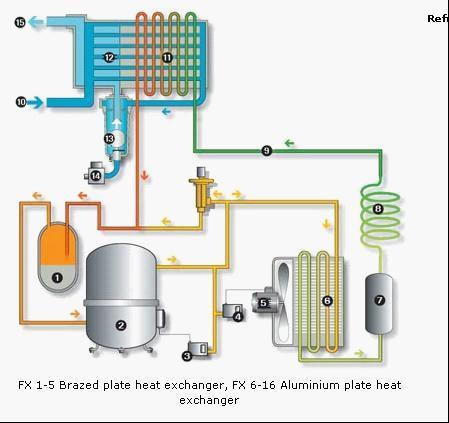
Flow diagram


Refrigerant circuit
1. Refrigerant separator : ensures that only refrigerant gas can enter the compressor, as liquid would cause damage.
2. Refrigerant compressor : brings the gaseous refrigerant to a high pressure and a high temperature.
3. Max. pressure switch(only FX13-15)
4. Fan control pressure switch(only FX13-15)
5. Condenser fan
6. Condenser : cools the refrigerant slightly so that it changes from gas to liquid; refrigerant is more effective in the liquid state.
7. Capillary filter : protects the expansion device from harmful particles.
8. Capillary tube : reduces the refrigerant’s pressure, thereby lowering its temperature and increasing its cooling capacity; the refrigerant is now almost all liquid, with some residual gas.
9. Hot gass bypass : regulates the amount of refrigerant passing through the air-to-refrigerant heat exchanger, ensuring a stable pressure dewpoint, and eliminating the chance of the condensate freezing.
Air circuit
10. Air inlet : hot saturated air enters the dryer and is cooled by the outgoing air via the air-to-air heat exchanger. Reducing the temperature of the inlet air reduces the load on the refrigerant circuit.
11. Air-to-refrigerant heat exchanger : transfers heat from the compressed air to the cold refrigerant, forcing water vapour in the compressed air to condense. The more effective the heat transfer, the cooler the air becomes and the more water vapour condenses.
12. Air/ air heat exchanger
13. Water separator : collects and drains off condensate from the cooled air flow. The more efficient the separation, the better the pressure dewpoint, as droplets which are not collected revapourise and degrade the pressure dewpoint. The collected droplets are reliably evacuated from the separator through an electronic drain.
14. Automatic drain
15. Air outlet : re-heats the outgoing air to prevent condensation on the factory’s pipework.

 English
  中文
中文  Español
  Русский


